|
801A AmplifierIntroduction to 801A amplifier After the introduction of the 801A tube, the tube characteristics, & output transformers, now comes the fun part, let’s talk about the design of 801A tube amplifier! This tube can be biased into class A and class A2 operation. I shall focus on class A2 as example specifically since this tube is capable of doing so and it sounds good! Check out these links on the past 801A topic: The tubes on the driver seat must be macho enough for this task. In class A2 801A amplifier operation, the 801A grid is driven positive and it will draw grid current. It is quite taxing for the driver stage and therefore care must be given on the driver stage design. Design methodology
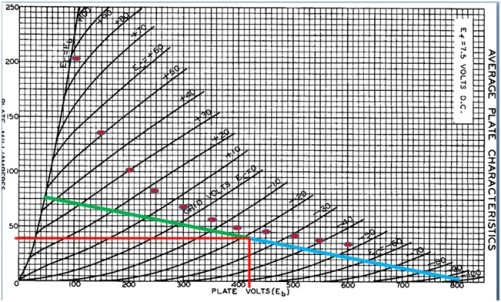
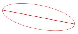
801A Vacuum Tube Datasheet: https://www.diy-audio-guide.com/support-files/801a.pdf . The red dots represent the maximum plate dissipation for 801A. Do not exceed this maximum plate dissipation rating of the tube or the plate will get too hot. This also applies for maximum plate current and voltage. All these will damage the tube and should be the limit we should push the tube to get more power and yet allowing the tube a good safety margin for long tube life span. In addition, we would want to operate the tube with the cleanest output – lowest distortion and highest linearity. The 801A amplifier sounds more relax if the tube is not pushed to the maximum too. There is one thing that we need to consider on using the above load line method is the practical or actual performance of the 801A amplifier. The load line used above represents ONLY PURE RESISTANCE load. Tube audio amplifier uses output transformer to feed loudspeaker loads, which have considerable reactance at various frequencies. When the real load is plotted, it is actually an ELLIPSE! In figure 2, the straight line represents pure resistive load and the ellipse represents the reactive load. This means the actual load line is a combination of reactance and resistance. Therefore, what we’re doing will be an estimation, a good one though. Figure 2
801A load line (class A2 801A amplifier) Figure 1 is the load line of 11,000 Ohm used for this amplifier. With every increase of 10mA of plate current, it will cause the plate voltage to drop by 110V, with 20mA of increase, the drop is 220V and so on. A straight line is drawn across connecting all the operating points representing the 11,000 Ohm load line. The operating point is chosen to be at 420Vdc at the plate and 40mA quiescent current. This gives a balance room for the grid to swing forward and backward from -22Vdc to -100Vdc and +50Vdc. This is equivalent to +/- 70V or 140Vpk-pk swing into the 801A grid. This will swing the 801A plate voltage from 50Vdc to 800Vdc (750V swing) on to a 10k / 11k load. This might not be the best operating point but it is chosen for (IMHO) balanced operation, given that the tube can swing the equal distance (symmetry) on both ends. Also, it has the best linearity since the plate voltage change with every grid change is quite constant across all grid voltages even at the extremes near +50Vdc and +100Vdc. If you’re familiar with class A1 amplifier design, you will notice that in class A1, the grid voltage will not go to the positive region. Only for class A2, the grid voltage will go to the positive region and draw current. 801A Amplifier Class A2 Output Power The maximum power represented by this load line, with sinusoidal audio wave form (as example) can be calculated like this:
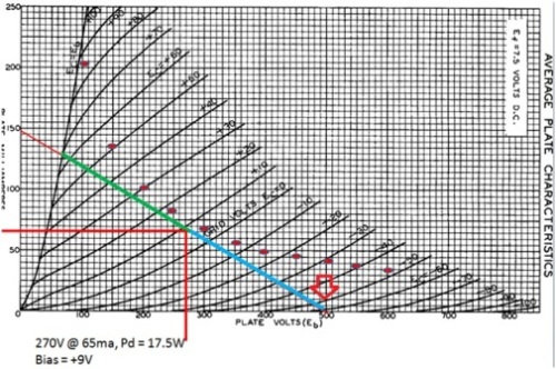
This is almost 2x the power we get from running the 801A at maximum ratings in class A1. In real scenario, we would not get so much power but it is still very cool, right? Figure 3
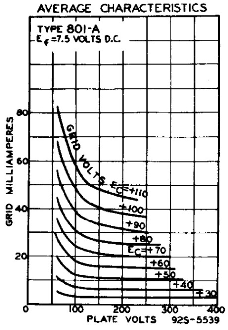
Another load line example A separate load line with lower load (3,300 Ohm) is drawn (figure 3) and it shows that at extremes of -50V (see red arrow), compression starts signifying non linearity of the operation => distortion! This is not desired for this 801A amplifier design and we should exclude that in the power calculation as well as operating point consideration. The quiescent value is selected to be at 270V @ 65mA to achieve symmetry between the positive and negative excursions. Let’s stick with only 1 operating point (figure 1) for this article: 11,000 Ohm load line used in the 1st load line diagram for this case. Class A2 notes When 801A grid goes into the positive voltage region it will start to draw current, as mentioned in the previous article here: When the grid voltage is high and the plate voltage is low, this is the class A2 region. Looking at our load line, highest grid current happens at ~50V plate and +50V grid voltage. Based on the supplied grid current curve, the grid would draw ~30mA maximum. We usually would not hit such level unless one always pushes the 801A amplifier to maximum or uses very low efficiency speakers.
Anyhow, this is a lot of current for the driver to supply! So sorry to say, sissy driver tubes do not apply for this 801A amplifier! Also, the grid current changes according to plate voltage and grid voltages. Therefore, we need a driver stage with low output impedance (much lower than 801A grid impedance) that can provide a considerable amount of linear and undistorted voltage / current (power) into the grid of 801A tube to overcome the changing grid current effects. Dropping 2-stage amplifier design Although 2-stage 801A amplifier design is the best, it would be tough to get a pre + driver stage that has the gain and low output impedance required for the design. If you can find the EC8020, then we’ve something cooking here. Other than that, I don’t see any triode driver that could do the job satisfactory without additional help. The other alternative solution that can overcome this is to have a step-up transformer at input stage to provide the gain needed something like a 1:4 or 1:2 step-up transformer for bigger triodes with lower gain. This can be applied to tubes like 6BX7GT or 6BL7GT. This works provided you’ve a source with low output impedance and high output voltage – or have a buffer or pre-amplifier stage connected between the source and this amplifier. This solution is not so optimal as well since we would want to configure the IT as 2:1 between 6BX7 and 801A to get lower output impedance at the driver stage. 3-stage 801A amplifier design consideration and selection 3-stage design is used in this design: pre – driver – power. This is the best fit so far. Several driver tubes come into the picture and it is chosen based on personal preference and taste. The others (some not mentioned here) work well too. For this example, the 6BX7 is chosen.
For pre-amplifier tube, virtually any tube can be used since the requirements here are quite low. Anything with a gain of 10 or more would do fine. My favorite would be the 5687 or 6SN7 variants. For the pre-amplifier stage, a lot of tubes can be used. Since 6BX7 is a twin triode, 1 triode can be used as pre, 1 driver can be used as driver. This save real-estate space on the amplifier since only 5 physical tubes will be needed on the amplifier, 2 for pre & driver, 2 for power and 1 for rectifier. Anyhow, the idea of using both triodes in the same envelope is not a purist methodology though, but it is absolutely understandable since a 3-stage purist design would need 7 tubes in total, 2 for pre, 2 for driver, 2 for power and 1 for rectifier. The simplest R/C coupling can be used on the pre to driver stage coupling. For a better design, an inter-stage transformer can be used to provide the additional gain / headroom for the pre to driver stage.
801A amplifier coupling method There are several ways of doing this, and the driver to power stage coupling needs to be taken into consideration too. Not all standard coupling works here. Since this is a 3 stage design, there are 2 couplings we’re looking at:
Pre-amplifier to driver stage coupling Inter-stage transformer coupling is recommended for consistency and better sound! RC coupling will be fine for cost cutting. Since we want to configure the driver stage to 2:1 for lower output impedance, we would want to increase the gain at the driver stage. Lundahl LL1660 inter-stage transformer is chosen here and configured to 2:45 ratio to get more gain. Lundahl LL1660 datasheet: https://www.diy-audio-guide.com/support-files/ll1660.pdf. Driver to power stage coupling Due to the current draw at positive grid voltage and no current draw at negative grid voltage, not all coupling methods could be used. Here they are:
Lundahl LL1671 Inter-stage transformer coupling is chosen here and (tips) configure to 2:1 ratio to lower the output impedance. Lundahl LL1671 datasheet: https://www.diy-audio-guide.com/support-files/1671.pdf . 5687 pre-amplifier stage design
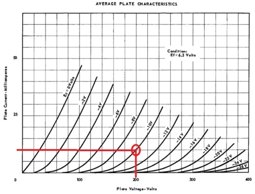
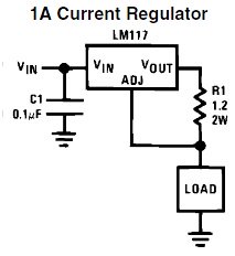
5687 Vacuum Tube Datasheet: https://www.diy-audio-guide.com/support-files/5687.pdf. The 5687 is a dual-triode in a single envelope. We can use both triode sections, with one as for left and 1 for right channel. Or we can use only a single triode section and leave the other idling for best channel separation. The 5687 is biased at 200Vdc at the plate and -10V on the grid. This will give the plate dissipation of 2W (200V x 0.010mA) at 53% of the maximum 3.75W per plate. Since the 6BX7GT is an easy load, we will not go extreme here. Lundahl LL1660 / 10mA is chosen here for the coupling job. It is configured as 4:4.5 step up to provide enough voltage swing for the 6BX7 to drive the 801A. Tips: if your system is lower in efficiency and need more gain + headroom, you can set the LL1660 to 2:4.5 step up to get more driving headroom for the 801A amplifier. With this, you can actually run the 5687 hotter, increase the quiescent current to 15mA. The 5687 is cathode biased with a constant source set to work at 10mA. This could be done using an LM317 positive regulator set as constant current source. See example below. For 30mA setting, just use R1 with value of 1.25V / 10mA = ~125 Ohm (refer LM317 constant current source figure). The load line for constant current source will be just flat / horizontal across the x-axis for the graph, leveled at 10mA. 6BX7 driver stage design
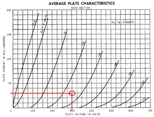
6BX7GT Vacuum Tube Datasheet: https://www.diy-audio-guide.com/support-files/6bx7gt.pdf . The 6BX7 is a dual-triode in a single envelope. We can use both triode sections, with one as preamp and one as driver stage, or we can use only a single triode section. We shall not use both triode sections here as I intend to drive 1 section to close to maximum plate dissipation of 10W to provide better driving capability to the 801A. The 6BX7 is biased at 300Vdc at the plate and -25V on the grid. This will give the plate dissipation of 9W (300V x 0.03mA) at 90% of the maximum 10W per plate. This gives the 6BX7 plenty of voltage swing and current to drive the next power stage. Lundahl LL1671 / 30mA is chosen here for the coupling job. It is configured as 2:1 step down to provide a low output impedance source for the 801A grid. The 6BX7 is cathode biased with a constant source set to work at 30mA. This could be done using an LM317 positive regulator set as constant current source. See example below. For 30mA setting, just use R1 with value of 1.25V / 30mA = ~42 Ohm. The load line for constant current source will be just flat / horizontal across the x-axis for the graph, leveled at 30mA. LM117 configured as a current regulator
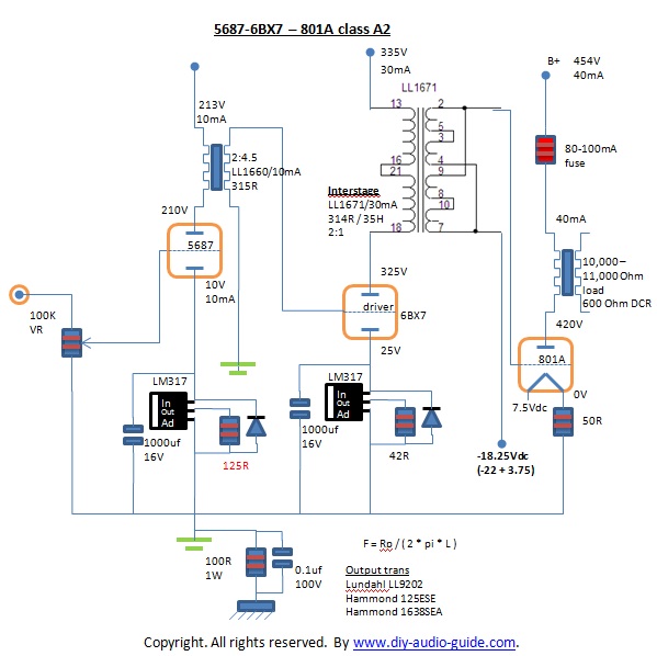
LM117 voltage regulator datasheet: https://www.diy-audio-guide.com/support-files/lm117.pdf. 801A amplifier power stage design For power stage, it is just the common fixed bias topology. A negative voltage source is provided to the secondary of the LL1671 inter-stage transformer to bias the 801A. A LM337 negative regulator will do the job nicely. The actual value needed at the LM337 regulator would be as follow since the 801A potential is elevated by the 7.5Vdc filament supply: (7.5V / 2) – 22V = 3.75V – 22V = -18.25V The filament is DC heating, fed with a 7.5Vdc double regulated (add a choke if possible) DC power supply. With 7.5V requirement, AC filament heating is not recommended if the matching speakers are of high efficiency type. It will be difficult to tame the AC hum when matched with high efficiency speakers. DC works fine with me without any sonic penalty being felt. Tips: add a 80-100mA fuse on the B+ rail to 801A plate to protect the tube. Constant current source Can we use constant current source load for the power stage? This is workable for class A1 but it is not possible for class A2 as it would not permit the operating point to move to the class A2 region because constant current source load will have a horizontal load line leveled at the bias current. It would be recommended for the pre & driver stage to provide lower distortion voltage swing to drive the 801A grid! Final 801A amplifier design
Alright, after combine all the sections together, the final 801A amplifier schematic looks like above! It will not be cheap though with all the inter-stage transformers in the design. Cost aside, the sound will definitely blow you away, satisfaction guaranteed! We shall talk about the 801A amplifier power supply and components recommendations in the next article. Ken 7/27/2011 Have you built any tube amplifiers?Do you have a great amplifier project? Share it! What Other Visitors Have SaidClick below to see contributions from other visitors to this page...
801 A2? Not rated yet Return from DIY Audio Guide / Electronics Components / 801A Amplifier to DIY Audio Guide
|
