|
Mains Filter
Mains filter – love it or hate it! Some swear by it, some hates it! There is not right or wrong. It really depends on your setup, your mains condition and all sorts of other factors. My mains are haunted with really severe noise pollution. I cannot listen to my setup without having the incoming supply filtered. Without any cleaning devices, the clarity suffered substantially. There is buzzing sound too at some time of the day. My initial solution for this was to use isolation transformer. The one I used is the discontinued Topaz Ultra isolation transformer. It worked very well and that served me for many years. Go to Isolation Transformer.But recently, situation got worse. There are more houses built nearby my area with heavy construction going on nearby. The noise pollution got worse, and DC is present on the power line that makes the transformer has annoying hum.
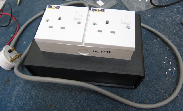
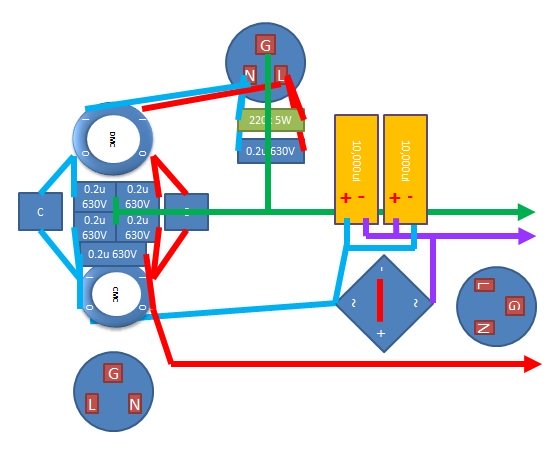
My initial thinking is to make a DC remover to connect it prior to the isolation transformer to kill the transformer hum. I did not expect the end results to be out of my expectations! Read on to find out more. Since I’m making the DC remover, I have added in additional EMI/RFI or noise filter to make use of the additional space available in the enclosure I have. From the above diagram, you can look at the block diagram of the DIY mains filter and DC remover. I have output socket with the DC remove and another without the DC remove for comparison. The left block contains differential mode choke, common mode choke, inductor, and film capacitors to remove all the garbage from the mains. The right block consists of two 12,000uF electrolytic capacitor and a bridge rectifier to remove the DC from the mains.
The topology is quite simple.
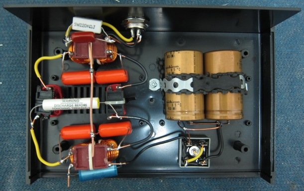
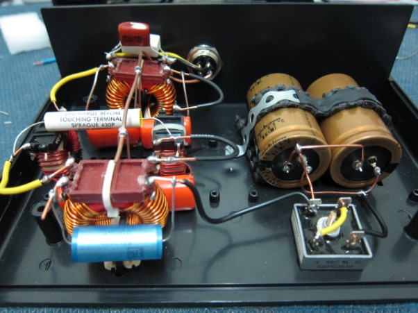
Components used here are all from my stash box – Rifa film capacitors, Spraque Orange Drop, Nichicon KG capacitor, and 40A bridge rectifier.
Top view – point to point wiring is used here since it is not that complicated to make.
Front view – solid core cables are used all over the place. The different colors of the capacitors are nice to the look.
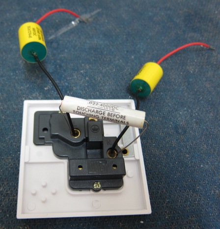
Apart from the DC remover / mains filter circuit in the black box; I tried installing additional capacitors at the socket side for more filtering. I tried it with and without the additional capacitors on the socket and they make no significant impact and were removed. Results I initially installed the DC remove / mains filter prior to the Topaz Ultra Isolation transformer powering the tube amplifier, DAC and CD player. Prior to serious listening, it was burnt in for ~24 hours with a table fan. The most obvious change is the mechanical hum emitted by the isolation transformer. It didn’t remove it totally but the audibility of the hum is much lesser, say by ~70%. Noise level is reduced and the system got darker, but something is wrong. It sounded rather anemic. The vigor and liveliness are gone, replaced with a rather weak and lean sound. Life is extracted out from the system. Too much of a good thing is bad thing, eh? I guess, maybe there was too much filtering. Why not I remove some? There goes the Topaz Ultra Isolation transformer in the chain. The audio equipment are connected direct to the DC remover / mains filter and I had further evaluation. Tadaa!!! The anemia is gone!!! Not only life is brought back, there are more improvements on the clarity and separation. It’s like I’ve added additional resolution to my system. I notice more things that I was previously unaware of. The separation of instruments became more obvious thanks to the darker and quieter background achieved with the DC remover / mains filter addition. I could no longer connect back the Topaz Ultra Isolation transformer. It has to go somewhere else, perhaps to supply only the source instead of the amplification. Things are not all rosy though. I noticed some hum with this new configuration on my subwoofer. Ground loop perhaps? I still need to do further troubleshooting. Till then! Try it and let me know how it goes! Ken What Other Visitors Have SaidClick below to see contributions from other visitors to this page...
DIY balanced power Return from DIY Audio Guide / Tips and Tricks / Mains Filter to DIY Audio Guide / Tips and Tricks Return from DIY Audio Guide / Tips and Tricks / Mains Filter to DIY Audio Guide
|
