|
Constant Current Source
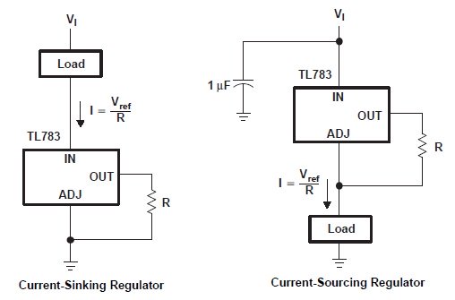
Constant current source or sink (CCS) is one of the very useful circuits for amplifier building. They can be used in power supply, act as loads, bias tubes, form a differential circuit and etc. I use it a lot in the tube amplifiers I built over the years. CCS can be created using discrete components, as well as using integrated circuits like the TL783, LM317, IXCY10M45, IXCY10M45 and etc. CCS with TL783 / LM317 family
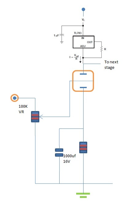
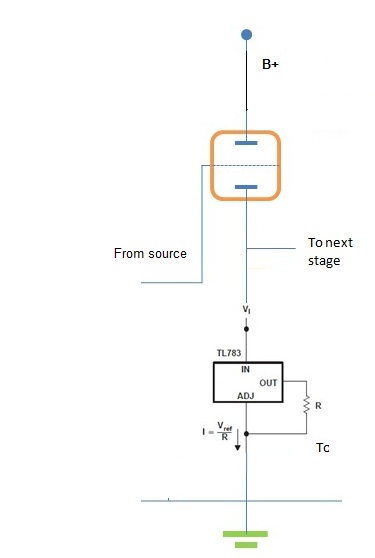
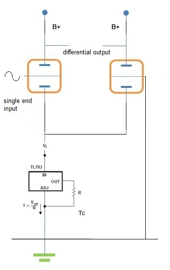
These 2 examples above configure the TL783 as current source or sink and can be effectively used in a tube circuit. The current sink can be used as cathode bias and the current source could be used as the load of the tube. This can be applied in buffer or line stage of a tube amplifier. Sample calculation, for a 10mA CCS: R = 1.25 / 10mA = 125 Ohm Let’s have a look at some sample circuits.
Common cathode line stage with constant current load.
Cathode follower buffer or line stage with constant current sink.
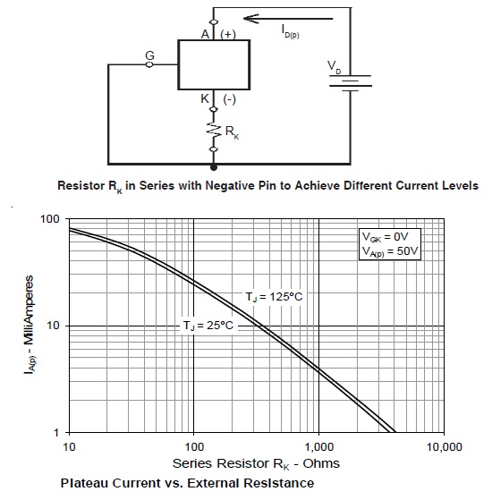
Single end to differential conversion The shortcoming with TL783 / LM317 family of CCS is the maximum voltage tolerance. The maximum for TL783 is 125V, LM317 is 37V, and LM317AHV is 57V. That is pretty low in vacuum tube circuit realm. Afraid not! There are alternatives, the IXCP10M45 and IXCP10M90 from IXYS! The IXCP10M45 is capable of handling 450V and IXCP10M90 is capable of 900V! Of course, there are tradeoffs to this. The IXCP10M45 and IXCP10M90 can only handle up to 100mA of operating current. 100mA is not a lot but it is sufficient to handle a single 300B or KT88 tube. Do take note that the continuous dissipation for the integrated circuit is only 40W. Handle it with care when you load the chip.
The biasing of IXCP10M45 or IXCP10M90 are not the same as the TL783 or LM317 family. It has no formula and requires slight manual biasing and experimentation. What one needs is just to vary the Rk to achieve different operating current levels of the integrated circuit. From experience, the operating current varies from sample to sample and requires manual slight adjustments to get it to match between channels. It would be useful to connect a 10-100 Ohm resistor in series with the G-terminal (control terminal) to prevent oscillations. Try it, and share with us you findings! We shall talk about discrete constant current source in the future! What do you think of this post?Do you have the same thoughts? Share it! What Other Visitors Have SaidClick below to see contributions from other visitors to this page...
Supertex LND150 Not rated yet Return from DIY Audio Guide / Electronics Components / Constant current source to DIY Audio Guide
|
